
spenting the next 3 months reinventing the wheel
Moderators: CaptPatrick, mike ohlstein, Bruce

Bob,
I saw the scan of the gear travel, looks like 1 3/8" each side of neutral. What is the trottle travel? If its 2 3/4" and you need 2 1/4" on the shortest throw at the engine it sounds like it should work. It would help to know how much travel is supported on the throttle side.
Just be happy you don't have a second or third set of controls to incorporate into the system.
KR
JP
1977 RLDT "CHIMERA"
JP
1977 RLDT "CHIMERA"
-
CaptPatrick

- Founder/Admin
- Posts: 4161
- Joined: Jun 7th, '06, 14:25
- Location: 834 Scott Dr., LLANO, TX 78643 - 325.248.0809 bertram31@bertram31.com
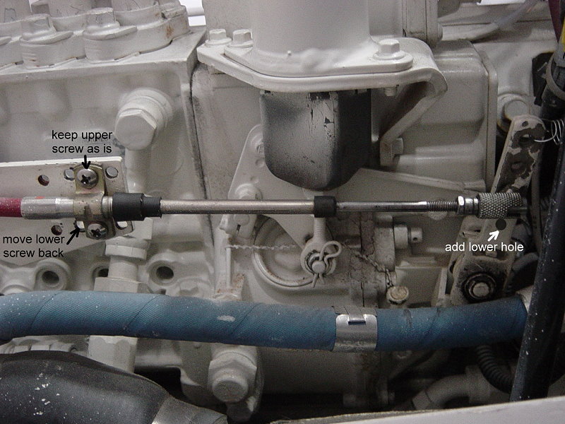

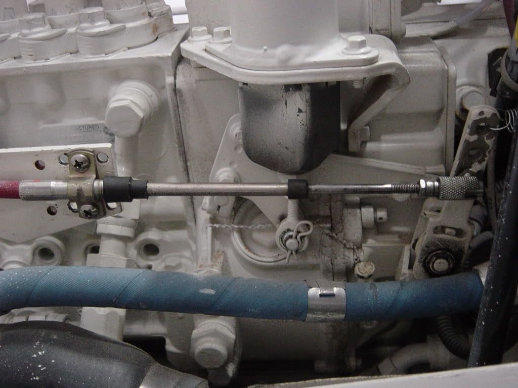
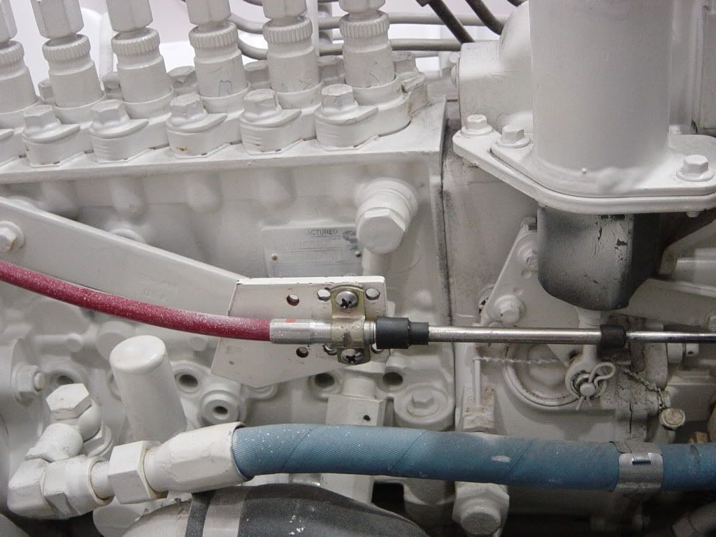
bob lico wrote:carl i took a photo of linkage .the top hole is a 3" travel the second hole is a 21/2" travel
and the third hole is a 21/4" travel.
Bob, the third hole gives 2-1/4 or 1-1/4" of travel? Sounded like you said it was too short, where you are at idle and go to the pins too quickly.
2nd hole doesn't have enough and the 3rd too much, put a hole between the 2nd and third hole...or am I missing something.
Last edited by Carl on Jan 27th, '10, 18:37, edited 1 time in total.
-
CaptPatrick
- Founder/Admin
- Posts: 4161
- Joined: Jun 7th, '06, 14:25
- Location: 834 Scott Dr., LLANO, TX 78643 - 325.248.0809 bertram31@bertram31.com
capt patrick i just can`t wait till you come up here in august a picture worth a thousand words. i went out of my way to make the least bent as possible with the cables . i even ran 3 cables down the starboard pillar and just the port thottle cable down the port pillar to avoid 180degree turn on gear levers . well be it as it may there is 0 bind in the cables and the thottles handles take a push with your pinkie and the boat leaps out of the water. forget touching the thottles in reverse. ever see a nuclear submarine broaching the surface well with the boat filled with fuel just touch the levers and the boat goes straight out of the water and comes down on bottom strakes! -------what contributes to this is that short throw on the thottle lever , those props don`t slip at all and vucan drive is instant power. i really need a 3" travel some how and use top holes in lever for smooth operation.
capt.bob lico
bero13010473
bero13010473

Bob, that's why I think you should make up carl's bracket very near your th linkage with a solid rod on ball/sockets so you can have a more linear throw. It seems to me if you go too short AT the throttle linkage your going to even more so have the "ballistic" effect, were as carl's bracket will allow you to use the third hole on throttle if made up right.
i guess i did not explain myself on the thottle lever. you cannot see in the photo there is a wound spring and backer plate at the bottom of the lever on the back side. you definitely can not drill a hole lower then the third hole.that mechanism is critical to the operation of the new style bosch 7100 pump.it supplies tension to the fuel injection pump rod.sim the lower hole from idle to wot is 21/4" . the exact the total travel from the bridge control head thottle is 13/8" about 3/4 speed.forget the two upper holes i can`t even get 1/2 thottle!!! unless bruce has a mechanical idea i will go with your drawing but maybe rocky`s idea with short piece of threaded rod.i still don`t know how long of a bell crank i need to gain about 7/8" travel.the boat will go to the "pins" 3125 rpm way way to fast but i would like it to go 2800 rpm.with the current props about 34 knots.
capt.bob lico
bero13010473
bero13010473
Okay, I see.
What if we attach a SS Flat Bar to the outside of the existing throttle lever with that Lower hole. Use the existing upper two holes for mounting and the lower hole could be tapped or countersunk from the back so it sits flush to the existing lever.
Then whatever we add to the lever in thickness we would have to move the cable mount as well to keep aligned.
Rocky, the bracket I drew up would be my last resort before gong over to Fly by Wire. The helm throw is fixed as is the throttle lever at the motor. All we are doing is changing the ratio, whether done with my bracket or relocating the hole closer to the pivot. My bracket would work, but adds needless complexity...just move the hole closer to the pivot where you get full Helm Throttle motion and Full Motor Throttle motion.
So Carl, now your saying to put a secondary plate/arm bolted to the outboard side of the existing pump arm so you can drill a lower hole closer to pivot point is what I see. But doesn't Bob not like the "ballistic" effect of pump arm moving too quickly? Keeping it simple I know, but well? The internals of the pump do not seem to support any standard cable operated systems as stated before so...
It's mechanical with two fixed motions, do whatever you want in the middle of those two motions the beginning and the end stay the same. All we are doing is is changing the ratio so the two have the same full range of motion. Helm Idle = Motor Throttle Idle and Helm WOT = WOT at the Motor. Nothing more.Rocky wrote:So Carl, now your saying to put a secondary plate/arm bolted to the outboard side of the existing pump arm so you can drill a lower hole closer to pivot point is what I see. But doesn't Bob not like the "ballistic" effect of pump arm moving too quickly? Keeping it simple I know, but well? The internals of the pump do not seem to support any standard cable operated systems as stated before so...

He needs a 2:1 180 degree bellcrank.
The arms on the bell crank are 180 degrees apart, the driver arm( cable from the throttle control head at the helm) should be attached 1.5 inches from the center of rotation of the bell crank. The driven arm (a linkage attached to the throttle lever) should be 3 inches from the center of rotation of the bell crank.
This will give 2:1 mechanical advantage, both in terms of travel and force required to move the throttle.
My 653's have this arrangement from the factory.
PM me for my email and I can send you a diagram.
-
In Memory Walter K

- Senior Member
- Posts: 2912
- Joined: Jun 30th, '06, 21:25
- Location: East Hampton LI, NY
- Contact:

Bob, Thank you for all the legg work on this one...Im facing the same problem your fixing...Cappy can you post a pic of that bell crank? My simple mind works better with pictures...BH
1966 31 Bahia Mar #316-512....8 years later..Resolute is now a reality..Builder to Boater..285 hours on the clocks..enjoying every minute..how many days till spring?

Just like on model aircraft controls. That is what I was thinking originally too.
In fact, here are some aluminum one for sprint cars that may work for you!! They even have bearings!!
http://www.google.com/imgres?imgurl=htt ... CBUQ9QEwBQ
These are cool looking and cheap!!
http://www.pitstopusa.com/SearchResult. ... oryID=4773
Control cable to short arm, linkage to throttle from long arm!!
Here is a source for stainless linkage parts: hiem joints, etc.
http://www.midwestcontrol.com/93.php
Rawleigh
1966 FBC 31
1966 FBC 31
-
Tony Meola
- Senior Member
- Posts: 6940
- Joined: Jun 29th, '06, 21:24
- Location: Hillsdale, New Jersey
- Contact:
-
Brewster Minton

- Senior Member
- Posts: 1795
- Joined: Jun 30th, '06, 07:44
- Location: Hampton Bays NY
- Contact:
not quite brewster to each his own. i cannot boil a egg, however my wife is a incredible cook . makes for a great marrige!!!
capy thats great i appreciate your effort i would love to see how you derived at 2 to 1 ratio .you illustrated a 180 degree bellcrank and rawleigh is showing links to 90 degree style.that would not give me the throw i am looking for .i no longer have access to a machine shop ,i must contruct in my shop with limited metal power tools.acquire ball bearings and press fit with machinest vice.
capy thats great i appreciate your effort i would love to see how you derived at 2 to 1 ratio .you illustrated a 180 degree bellcrank and rawleigh is showing links to 90 degree style.that would not give me the throw i am looking for .i no longer have access to a machine shop ,i must contruct in my shop with limited metal power tools.acquire ball bearings and press fit with machinest vice.
capt.bob lico
bero13010473
bero13010473
Those are great sources Rawleigh. It looks as though the Solo series controls don't allow switched orientation for push/pull? So you would have to use more of an "in line" ratio change like below instead of a 180 degree, for the action would reverse using 180's unless we could get Capy's picture of his set-up already used and R&D'd.
[/img]
[/img]
or you could just attach the cable to a lower hole on the lever.
You'll get the same results, think about it.
2:1 at the lever (AKA- moving hole closer to pivot) or somewhere in between is still 2:1
You may want to tweak that ratio abit...2:1 would double the throw of 1-3/8 to 2-3/4"...that's too much or not enough throw when utilizing the existing lever holes. At that point you could then drill a hole in the lever to utilize the full range of motion...but seems to be some resistance to that method.
Hi Carl, so even if that first arm before the pump is longer in length as shown, would not give the effect of more linear response on pump and more throw, if we adjust ratio at first arm? Seems like it would work from the lengh of the first arm and maybe distance change on cable hole location. Still a problem of too quick from going lower on pump arm.
Sim, but you won't gain mechanical advantage, in fact you will lose it.sim wrote:or you could just attach the cable to a lower hole on the lever.
You'll get the same results, think about it.
2:1 at the lever (AKA- moving hole closer to pivot) or somewhere in between is still 2:1
You may want to tweak that ratio abit...2:1 would double the throw of 1-3/8 to 2-3/4"...that's too much or not enough throw when utilizing the existing lever holes. At that point you could then drill a hole in the lever to utilize the full range of motion...but seems to be some resistance to that method.
Bob needs to increase throttle position RESOLUTION(or finer position control) and reduce the input force at the helm
Moving the hole closer to the center of rotation does allow for full range of motion but at what cost??? the linear force required to achieve the same torque requirement goes up, not down....plus a shorter lever here limits RESOLUTION....moving 1 3/8 inches from idle to full throttle with a huge effort, is dangerous with his no slip props...
Easiest way to gain Resolution is to just increase the lever arm at the helm,that attaches to the cable itself, but bob said he can't do that due to space limitations( but to reduce force you would need to move the cable down on the engine throttle lever farther away(win-win, reduce force req and increase resolution)
...another easy way to gain mech advantage is to increase the lever arm where the operator attaches his hand to apply the force...double the length here will halve the input force but not increase the resolution of the motion, again you need a longer throttle arm at the engine...to achieve win-win.
The bell crank will do both, reduce input force and increase position resolution, while not requiring helm throttle reconfiguration.
Can you tell I have some free time??
Regards,
Paul
P.S.
The diagram I have is a powerpoint slide so if you PM me with your email address thats what I will send you.
Last edited by capy on Jan 29th, '10, 10:53, edited 1 time in total.
sim ,rocky if i use the top hole in the fuel injection pump lever and dril mutible holes in out 2to one lever i might find the happy medium. i don`t want you to think i am i am overstating the enormus instant power of these engines and i really don`t want to hyjack this thread and go on to tell you why so let me say ;this is NOT the cummins powered boat your friend have and you went for a ride.i really want to have a smooth thottle response like a normal boat so the top hole in the lever with 3" throw is a criteria that i would like to address at the same time as having full thottle.
capt.bob lico
bero13010473
bero13010473
I'm confused.
Bob what are you after?
I thought you just wanted to utilize the motors full throttle range, 0-100% and make that coincide with the helms full range of motion.
If you want resolution you will loss full travel. AKA- can't hit the motors pins that is if you start from a low idle. I thought that is what you have now and do not like it because you cant' hit those pins.
Mechanically, I think your going to have a trade off...full range for resolution...can't have both.
Do you have any room to move the cable connection further out at the helm, 1/8 would do you wonders.
-
In Memory Walter K
- Senior Member
- Posts: 2912
- Joined: Jun 30th, '06, 21:25
- Location: East Hampton LI, NY
- Contact:
sim in order to go to 2700 rpm not the pins the boat will do 12knots at idle if i adjust linkage to go to pins a person standing in the cockpit would fall down just by shifting to foward ,downright dangerous docking. there are other consideration also the boat is 90% fishing offshore and 10% pleasure boat with family. bring a tuna to the boat and leave in idle forward and the mate yells back what am i capt. ahab trying to gaff at even 8knots is a bitch .so i detune engines ,reduced prop pitch and the boat still will go 27knots at 2300rpm but know i can idle at 5.2knots.forget about going top speed i just want 600rpm idle and the ability to go 2800rpm thats flying!the pins are 3125rpm never want to go that fast.
capt.bob lico
bero13010473
bero13010473
Hi Bob, it seems ridiculous to have only a total of 1 3/8" of cable movement from Solo series, but these ROUGH measurements will give you idle to full throttle (3" at pump top hole) with only 1 3/8" total cable movement. That is, if the 3rd hole to pivot on pump is 2 3/4" on center.
Maybe we should run this by Carl and Capy first before you start fabbing it!
[img][img]http://i379.photobucket.com/albums/oo23 ... inkage.jpg[/img][/img]
Maybe we should run this by Carl and Capy first before you start fabbing it!
[img][img]http://i379.photobucket.com/albums/oo23 ... inkage.jpg[/img][/img]
Another thought Bob I know you've been asked before but by chance would the Solo series have a different "cam action" at the pivot plate that would give that extra throw, You could simply bolt in place of original pivot plate the company has, that just might be too simple though, ha ha.
Have you expired all your options on that end of system is the question?
Have you expired all your options on that end of system is the question?
Here is an interesting progressive arm that when at idle speed, the pump would have half the movement of the helm input, until you get about half throttle, then it is direct.
[img][img]http://i379.photobucket.com/albums/oo23 ... inkage.jpg[/img][/img]
[img][img]http://i379.photobucket.com/albums/oo23 ... inkage.jpg[/img][/img]
rocky you really got into this .i really appreciate the input.i should further explain the situation. every 31 bertram in the world has a engine (gas or diesel) a sae adapter and a flywheel ringear. from that point they use a torsional adapter (same as a pressure plate in a car)this adapter has spring around the perimeter to absorb the torque when you put the boat into gear. my boat has vulcan drive . this drive uses a machine steel sae adapter then a solid torsional plate.super strong,no slip and no spring rattle.however you need a smooth thottle or you have the raceboat effect.this shortining of the fuel injection pump lever contributes to the boat launch with just a touch of the helm thottle arm.getting back to your sketch i like the idea of using the upper hole in the lever to give a more infinite increase in rpm.
capt.bob lico
bero13010473
bero13010473
Thanks Bob and Carl, yeah Bob the question was about your helm control, and if the manufacture had a "pivot plate" that would allow more through to cable from the start, but youv'e probably expired that road already.
Yes those measurements could be scaled down with same effect too!
I was up quite late last night thinking how could I simulate a progressive throttle like that of an older injected car with an oblong cam a cable rides on the edge of. Toyota didn't want the customer to have "ballistic throttle" either! Thanks guys.
i did rocky believe i try everything and to add to the stupidity is a design with 13/8" forward and 13/8" reverse to match gear throw . think about it !!! why in hell would i want to go 2300rpm in reverse like if you could it would be 27knots. the helm is machine to perfection with top quality stainless 316 but the limit on the thottle foward throw is on called for.
capt.bob lico
bero13010473
bero13010473
-
In Memory Walter K
- Senior Member
- Posts: 2912
- Joined: Jun 30th, '06, 21:25
- Location: East Hampton LI, NY
- Contact:
A single lever control with an equal throw for reverse as forward doesn't sound right (and doesn't make sense) unless it's designed so the same unit can be used on either side . I'm sure you have checked the manufacturer but there SHOULD be an internal adjustment as different engines require slightly different throw lengths. Is it that at the entry from neutral to drive the engine isn't slow enough for a smooth (non jarring) contact with your Vulcan drive?
walter go back to page two of this thread there is the factory side view of the helm unit. note the thottle lever ,there is not a damm thing you can do with it. incidently there would not be enough side clearance to " attemp" relocating that center pin and the calibration would never work . that is the funtion is to go into gear then further pushing of the handles starts to increase rpm.
capt.bob lico
bero13010473
bero13010473
O.K. then Bob, those dimensions will work as is if you have the room, or can shrink that design with same results. I have the same cable straps for my Morse controls so I just gauged the length of your pump rod from that reference. We just had a baby so I've had some time off work to do stuff, whish I had more or I'd build this thing up only thing is we're on the other side of the country! Let me know please if you do need to shrink that, I'll re-configure the latest drawing or Carl could take off with it perhaps
Bob,
It really makes you wonder what they where thinking when they designed up that Control. Unless it was never meant to be used on your engine.
Non-the-less, if Solo can't /won't offer you a fix and moving the hole closer on the lever is out of the question. The balls in your court. If you decide you want to go mechanical and need something...give me a holla if I can help. Carl
carl i am calling and there not answering and when they do a elderly women tells me someone will get back to me-----enough back to the problem these units are sold as universal and the end user here is cummins same as yammar in thottle lever throw. i will go mechanical but there is limited room in the engine around the fuel injection pump.i have fuel coolers to and from pump that are in the way but using your first diagram in combination with rocky`s solution i would like to put this bell crank assembly under the bridge with the cable to the engine moved back on the bracket and up to hole at top of lever. plenty of room under bridge to do just about anything with lingage but would need a cable or rod lingage about 2' from helm .is this doable??
capt.bob lico
bero13010473
bero13010473
Hi guys, so the only way I can see a remote system would be with two cables , one two ft cable to plate from helm and you would need to have two arms just like the drawing but what was the pump arm is now the arm driving the cable to the pump arm. (should have same results). Now could be the opportunity to make this up without even being at the boat, at least the plate mechanism portion anyway, then just bolting it up were you want it and final adjustments. Let me know, I'd be happy to make a model, you could build from?
Who is online
Users browsing this forum: No registered users and 296 guests