Hull Repair -- Working from the inside.
It's not uncommon to need to repair a section of a hull because of damage, delamination, or simply just to glass over an unwanted hole left by a removed through hull fitting.
The main problem with hull repairs lays in maintaining the exterior shape and fairness, especially above the waterline. This article will lead you through a hull repair on a 31 Bertram that has been done from the inside of the boat.
Here's the problem that existed when the boat was received for restoration/customization:
On the starboard side, the hull was delaminated in an area of about 5 square feet.

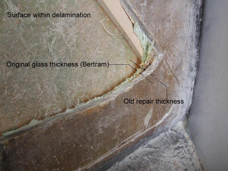
Careful examination indicated that the delamination was approximately half of the thickness and only a slight distortion existed on the outside of the hull. Something that is easily dealt with using standard a fairing processes.
While the original reason for the delamination was found to be two fold, there was no exterior penetration that would require any glass work. The damaged area was readily accessible from the inside, so making the repair from there would accomplish the task with as little tale-tale indication of there ever being a repair made.
Working from the inside would seem to be a more arduous task, and grinding fiberglass inside of a tightly enclosed space is certainly not a fun pastime. But the problem encountered by external repairs is simple:
The original polyester and fiberglass hull has cured & shrunk over many years. Any new glass work on the exterior will continue to cure and shrink for years to come. This would lead to print through of the glass and a negative depression within the area of the repair. It might look good in the beginning, but after a couple of seasons the area would stand out, even at a short distance, to the naked eye.
So here we go...
The first step was to identify the area of damage, in this case using a small hard mallet to sound out the hull. As the sounding progressed, marks were made at the points where solid glass began to resonate the existance of the delamination. Solid glass has a hard crisp tone under the hammer while delaminated glass has a muted dull tone. Once sounded, a drill was used to spot the perimeter so that it would be clearly visible from the inside.

Using a high speed angle grinder fitted with a narrow kerf metal cutting blade, an X pattern was cut into the fiberglass, being very careful to only cut deep enough to find the delamination layer. There were two ways that I used to detect this hidden layer: One, I can feel the difference in the cutting as the blade finds the proper level. It will seem to catch somewhat similar to the feel of a drill bit when it first penetrates the material it's drilling through. Secondly, there will be slightly more light that shines through as the correct depth is achieved.
Once this X incision has been made, I could use a chisel to lift up a corner. I then cut off a small triangle to access the thickness of the fiberglass being removed & better see the underlaying surface of the delamination.

Below is the first full section removed. There was virtually no bond between the layers...

Wooden wedges were used to raise the segments & allow a bit more clearance for the grinder blade. I slowly worked my way around the four segments and after an hour managed to totally remove the inside layer of delaminated glass in 6 sections, shown here laid out on the engine box.


Now there is a small amount of delamination still left around the perimeter of the cut out. This is removed by grinding back and at the same time scarfing the perimeter back by about 2". On any repair, blunt edges must be scafted to a minimum of a 12:1 ratio. That means that whatever the thickness of the edge is, the amount of scarfing that must be made is 12 times that thickness. As in this case, a 3/16" thickness needed 12 x 0.1875 or a 2.25" scarf.


With the delaminated interior layer removed, it was obvious that there were two reasons that created this situation. First, the original layup by the manufacturer seems to have not been thoroughly wet out, bubbles left behind, and maybe even some contamination between the two courses of glass was present. So the base delamination was there from the beginning, but was tight enough not to be detected.
The second problem was some superficial damage to the hull just above the chine, that happened during a previous ownership. This blunt force trauma created enough deflection to the hull that the weak bond between layers popped loose.
It was obvious that there had been an attempt to repair this damage, & correctly from the inside, but totally ineffectually executed. No attempt had been made to remove any delamination & the rather heavy patch that was applied only covered what was some visible cracking in the surface of the original glass. A bandaid at best and probably a rather hefty repair bill to the owner. Kind of like treating a broken pane of glass with a thick layer of Scotch tape...
Once ground down, a paper pattern is made that well overlaps the area. Rather than glass up directly over the prepared area, I will make up a fiberglass & polyester panel to conform. This panel will be laid up with a schedule of 12 oz biaxle & 1 1/2 oz chopped strand mat on my glass top table.


Once the layup has cured for a couple of hours, but still green, it is carefully removed & moved to the boat.


Below, I adjust it into place and screw it to the hull at a center point. Then mark to better configure within the scarf, but fully covering where the delaminated area was.

After trimming and re-adjusting the center screw placement, I've drilled pilot holes radiating out from center. Starting around the center, working outward, the panel is firmly screwed into place. By doing this while the patch layup is green, the panel will finish it's cure and better hold the shape of the hull flair when I'm ready to epoxy bond later.
I'll let the panel remain in this tensioned position for about 18 hours while final cure is achieved.

Now, why didn't I just lay up the hull directly?
I could have, of course, but:
1. It's far easier, cleaner, and more controllable to lay up on a shop table than on a semi-vertical hull.
2. I want the bulk of the patch to be polyester/glass to conserve on the expense of epoxy.
3. New polyester only has a mechanical bond on old polyester. Epoxy, being a true adhesive, will bond the panel to the old glass far better than any bond could be achieved using polyester.
So my plan of attack is to create a strong, void & bubble free polyester panel, that will be bedded with thickened epoxy, and then tabbed around the perimeter with epoxy & fiberglass. The resulting repair will be very high strength, exceeding the strength of the original hull, even in a non-damaged area, by choice of materials. The cross section of the repair will closely match the hull thickness in similar, but un-repaired areas. Finally, the repair will be more economical than epoxy glassing directly to the hull & with less shrinkage to potentially print through over the coming years.
Installation: Prep, prime, & bed
The following sequence of images show the necessary steps in installing the panel with thickened epoxy.
After removing the dry fitted panel, the side to be bonded to the hull has been thoroughly sanded to remove any trace of mold release from the surface & to also give plenty of tooth for the epoxy to grab onto. (Note the warp of the panel which was developed by curing in place against the hull.) The perimeter has been scarfed to closely match the scarf of the hull.


As always, bedding surfaces are primed with mixed, but un-thickened, resin.


A thickened mix is prepared using Cabosil only & to the consistency of mayonnaise. This is applied to both bonding surfaces, (hull and panel), using a 3/16" V notched trowel. There must be enough epoxy laid down to fill all voids & low spots, resulting in good squeeze out at the perimeter of the panel. Remember to Work the screws from the center of the panel, radiating outward to the edges of the panel. This will progressively move the epoxy toward the edges of the panel.


The squeeze out material is faired to the panel with a plastic spreader.


Once fully installed, there should be no light halos & the overall appearance of the panel should be dark, indicating a complete void free bedding. Here the only bright light transmissions are from un-used screw holes.

Clean up any excess epoxy & be sure to clean out any screw heads that may have epoxy on the slots. You really do want to remove these screws later...

From the outside of the boat, at this stage, the hull looks like a briar patch, but after the epoxy sets and the screws are removed, only tiny holes will be left & be faired over. The screws should be removed only after the epoxy has achieved a good firm bond, but before a full cure has taken place. Generally about 12 - 14 hours on a cool day, 6 -8 hours on a warm day. Thanks to my hot Texas days, (97 today). my cure time before removing the screws & grinding was only 4 hours...

The next step will be to tab the perimeter of the panel to the hull. This was done using 12 oz biaxle cloth & un-thickened epoxy.
To begin the tabbing, first grind the perimeter to develop the same margin as on the hull, smoothing away any remaining epoxy high points left by the spreader. The resulting perimeter should have a slightly concave configuration so that the tabbing will lay into it, & won't be cut into when the edges are feathered back. The diagram below shows the graphic progression:

And, the following images show the actual process:
The perimeter is ground into the required concave pattern...


The biaxle tabbing is cut and dry fitted...

Wet out of the tabbing is done on a sheet of waxed paper...

Tabbing laid down and de-bubbled...


The tabbing edges are feathered...

The remaining below surface portion of the tabbing is faired over with filled epoxy & the interior repair has been completed, other than to sand & smooth out the fairing. (A speck of green dye was added to the fairing mix just for more noticeable color contrast.)

The outside screw holes are filled.

This is all that's necessary in terms of sanding the patch since the interior hull will be upholstered with foam backed vinyl.

A quick sanding of the outer hull, leaving the rest for final fairing and paint.

In final review, this repair went smoothly and as expected. The total elapsed time from start to finish was 3 days, with a total labor time of 10.5 hours. There was minimal trapped air between the panel and the ground down hull; only 3 very minor spots beneath screws, each about the diameter of a dime. Sounding the outer hull with a hammer produced no change of sound between the un-damaged hull & the repair area.
Mission Accomplished!
Granted, this "bonding in a plate" technique is somewhat unorthodox for this type of repair, but not a new invention. It may not lend itself to all other similar hull repairs, but I am very pleased with the results.
The following question was posed through email during the process:
Capt Pat, thanks for the great read.
I have one question though in regards to this statement. I ask only thru my background in machining and welding and not sure if it translates into fiberglass. When making a repair that is stronger then the original I have found the repair area does not flex evenly with the original materials and cause spots of fatigue where the two come together, or the extra strength will cause another area to flex and break. Anyway, I usually try to match the repair strength with the original, unless the area is a weak spot to begin with, bad design or using it's being used in a method other then originally intended.
So why make it stronger then the original? The original did not fail because it was weak, it failed because it was manufactured incorrectly. All I come up with is that the material will flex at the same rate but just less resistant to fatigue, thus making it a superior repair.
Sorry for the questions, but these are the things that get me thinking.
Regards,
Carl (username SIM)
-----------------
Carl,
Your observation is true in regards to overly "beefing up" a patch, and especially true of a welding situation.
On this fiberglass repair, the higher strength will come from the choice of biaxle as opposed to 0/90ş roving & the use of epoxy to bond & tab the panel in place. The overall thickness of the finished repair area will be very close to the overall thickness of the original manufactured hull. The ability of the hull to flex evenly across the joint perimeter & through the repair should be well within tolerance. Also the scarfing of the joint overlaps prevents a hard edge line, transmitting the flex forces evenly over the joint.
I'll try to clarify this more in the finished article and design a graphic to illustrate the right & wrong way to develop a transition without causing a hard spot.
Thanks,
Patrick
|| Purpose | Bertram31.com Features | "Fortuna/Ishgair" ||
|| Links | Images | Guest Log | Bulletin Boards ||
|| Custom B31 Parts Available ||