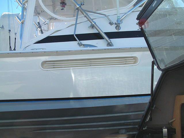
New Style Bertram 31 Side Opening Air Boxes
Redesigned 09/2009 -- I have changed the design of the New Style Air Boxes by excluding the exterior bead arounf the opening. The boxes now have a flange, similar to the Original Style main baffle, and are installed from the inside
These ready to install Air Boxes, for side
induction air are specifically designed for the
Bertram 31.
(Shown here is Ricky Saunders' "Miss Olive")
Principal features include:
Optimum air volume
Up to 400 hp diesel. Diesel engines need far more air than do gas engines. The rule of thumb for diesel
engines is 1/2 square inch of free air delivery per each rated horse power at full RPM.
Noise reduction
Air delivered from hull
sides, below the shear line. With proper sound insulation in the engine box, all engine noises are reduced to under 30 dB, even on the Cummins 250/300 installed into the Bahia Mar model
Cleaner air
Even in a head sea with smoky diesel engines, the inducted air is always fresh. No ingestion of
engine exhaust, as is possible with cockpit air supplies.
Visual appeal
Another "Signature Design", the simplicity of lines complements the B31 profile and the "Drop-In Design" makes installation very easy even on a newly painted hull. No need to repaint the hull after installation!
Price per pair: $1,750.00 USD plus packing and shipping. (USA east coast shipping & handling averages $125.00 using UPS or FedEx ground.)
Minimum Deposit Required: $800.00
Shipping time: Generally, under 4 - 6 weeks.
Overseas shipments available, but must be paid in full at time of order. Payment by wire transfer only, shipping costs will be calculated based on shipping address.
How they work:

(Click for larger image)
 (Click for larger image) (Click for larger image)
Kit will contain the following:
Port and Starboard Air Box Assemblies
Each box has 3 elements:
Main Box
Air Stack
Baffle Grill
Foam installation spacers, wedges, and mounting hardware
Template to cut side holes
Can be used for both sides, simply trace
the hole to be cut.
4 printed pages of Installation Instructions and tips
Technical Support: Via phone, email, or
Bertram31.com General Discussion Board.
( http://bertram31.com/newbb/ )
Construction of the Air Box is 100% polyester resin and fiberglass. The baffle assembly is made from
structural fiberglass plate. The standoffs are clear cast acrylic.
Installation should be done using epoxy
resin and Cabosil. Addition of fiberglass mat or cloth
as tabbing is not necessary, but never hurts. An alternative
adhesive would be methacrylic, (super strong and requires less
surface prep or thickening, but expensive and more difficult
to obtain in small quantities)
The Air Box has been designed to give
optimum free air delivery for any engine up to 300 hp.
Acceptable air delivery for engines up to 400 hp. Air
delivery is calculated for diesel application, so any
size gas engine is more than covered. Air delivery is 150 sq. inches per box.
Installation Instructions and Options:
Installation will be a 3 part project and can be accomplished even with the engines in place. It is recommended that all bonding be done with either epoxy or methacrylic adhesive.
Parts list:
2 pcs - Main Air Box
1 pcs - Hole template for hull cut out
2 pcs - Fiberglass and acrylic baffle assembly (includes 12 1/4"-20 SS machine screws and fender washers)


The New Style Air Boxes have been redesigned...
As opposed to the first design of the New Style Air Boxes, the redesigned box now has a wide full circumference flange and installs from the inside of the hull, rather than from the outside. This change has several advantages over the first design.
1. Quicker installation and fewer installation steps. The box now comes fully glassed as a single unit.
2. Cleaner fully flush look, without a fiberglass seam to deal with.
Installation of New style air boxes:
Depending on the type and horse power of your engines, the space between the top of the air stack and the underside of the gunnel can be critical.
For lower horse power engines, (diesel below 270 hp), and higher RPM engines such as Yanmar and Styer, a minium space of 2" between the top of the stak and the underside of the gunnel is required.
For higher hp engines, 300 hp and over, and lower RPM engines, such as Cummins, Cat, and Detroit, a minium space of 3" between the top of the stak and the underside of the gunnel is required.
1. To find the proper placement for the cut out, hold the box against the inside of the hull, measure the space above the stack, keeping the box a level as possible. Drill a single 3/32" hole through the hull corresponding with either end hole on the box. One hole only.
Set the box aside and move to the ouside of the boat. Screw in one of the deck screws provided in the kit. Remove the screw and re-screw with the template in place. Level the template with the shear line of the boat and tape the other end of the template in place. Step back and look at the template in relation to the boat. when it looks correct to you, drill and screw in the other end. Drill the other 6 holes according to the template.
Mark the cut out with a pencil or fine tip marker. Remove the template.
Accurately determine the position of the hull cut out and screw the hole template to the hull. Be careful that when drilling the holes corresponding to the template, you drill at a 90ş angle. Drill every hole, a total of 8 as per the template.
The screw holes in the template match the screw holes in the air box flange. Dry fit the air box to the inside of the hull and check for proper alignment and fit. The inside of the hull should be ground, removing any major surface obstructions in the area of the air box flange.
2. Using the tool of your choice, cut out an initial hole, staying inside of the marked line by 1/8" to 3/16". Replace the hole template onto the hull.
3. Using a router and a 1/2" flush pattern bit, (picture), trim the hole up to the template. Remove the template.
4. Mask off the interior opening of the airbox, epoxy prime the mating surfaces of the flange and hull. Allow the un-thickened epoxy prime to cure to the point that it is tacky.
5. Mix a batch of thickened epoxy to the consistency of peanut butter. Coat the entire air box flange face with a thick enough layer of the epoxy to assure a squeeze out of material around the full circumference of the flange when the air box is screwed into place. Don't tighten the screws overly; epoxy likes a little thickness in the joint. Tighten the screws only to the point that they make final contact. Clean up all excess epoxy, both inside and out. Remove the masking while the epoxy is still wet.
6. With this stage of installation complete, prep, fair, and paint as desired.
7. Install the baffle assemblies. Do not over tighten the panhead machine screws that hold the acrylic standoffs. A dab of 5200 on each screw thread and a snug tightening will assure a secure assembly.
Options Notes:
Inside reinforcement of main box: It is not necessary to use fiberglass tabbing to the inside of the hull, but at the very minimum a generous fillet of epoxy should be added completely around the joint. On hulls later than 1972, the thickness of the layup is significantly thinner than on earlier models. I would recommend adding a strip of 1/2" or 3/4" plywood both above and below the box. The strips should be about 3" wide and run from bulkhead to bulkhead. The bonding surfaces should be ground down to bare fiberglass and cleaned with denatured alcohol & primed. Bed the strips in with thickened epoxy, and coat the exposed well with straight epoxy. These strips will add back any vertical rigidity lost by cutting the hole for the box.
Please feel free to contact me for clarification of anything that you're not sure of or need consultation on. 1.325.248.0809
For additional information, please contact:
Capt Patrick McCrary
834 Scott Dr.
LLANO, TX
78643
325.248.0809
bertram31@bertram31.com
|
site creation and maintenance by:Capt Patrick McCrary
©
3640 Investment Ln. #15, West Palm Beach FL 33404
Telephone 325.248.0809
Web site questions or comments to:
bertram31@bertram31.com
|
 (Click for larger image)