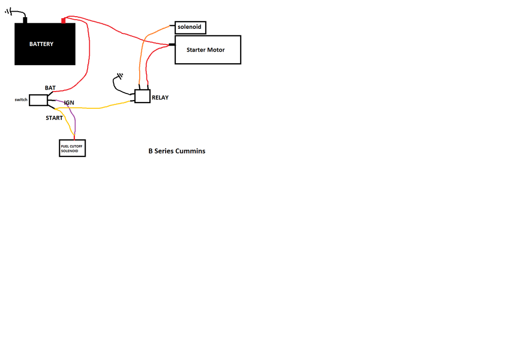
I did some research and was going to wire my starting circuit according to this diagram I made up. I figure the starter itself has its own solenoid but have heard that it may get a better 12volt feed to it if you run it through an additional solenoid.
I was thinking about doing it with a heavy duty relay to accomplish the same result. This would allow a constant 12 volts to the starter solenoid, via the relay. This allows very little strain on the wire coming from the bridges ignition switch.
I had also heard that adding a wire from the "starting" terminal to the IP Fuel Shutoff plunger switch will allow smoother starting and will only get power while cranking and then the power will remain on with ignition "ON".
I dont necessarily like having more wiring and another thing to break down but I think this may have been done by others with positive results.
According to the diagram, anyone see anything bad???
Frank - your relay is not necessary and just one more thing to fail....the current needed to trip the starter solenoid is minimal, well within the capacity of the ignition switch, as is the current to the "run" solenoid in the injector pump. One of Cummins' strong points is its simplicity.
My thoughts were with you Viceroy and that was my original intention. When I tore down the engine for the rebuild the original wiring harness has a solenoid wired into it.
That is in addition to the solenoid that sits atop of the starter which did not make sense to me.
These engines are a new install for my vessel and never ran them before thats why I am trying to make heads and tails of the wiring.
The fuel cut-off only requires a 12v source and to keep it simple can be wire to the on/off circuit of the ignition switch.
Some guys on the 4BT forum (non boating guys) made the suggestion on adding the "momentary on" to the starter circuit to insure no fluctuating of having too much draw from the starter solenoid and possibly causing the fuel cutoff to not have enough voltage to hold the plunger up.
The reason for a primary(smaller) relay or soleniod is to reduce the current draw on the start switch or push button.
This allows the engine maker to reduce the size of the start wire to the panel and also prevents burning the contacts in the switch.
Some starters have a good size solenoid on them and when the power is applied and let off the induction can spike voltage from 12v to a few hundred volts which is why some relays you'll see a diode across the coil terminals or resistors or capacitors to keep the spike from burning the switch contacts or burn out other components.
Most all your modern engines for years have come with dual soleniods or a relay and solenoid on the starter.
Cheaper switches and reduced awg size reduces costs thus more profits.
Sorta the reason many switches I see now a days are junk in my opinion.
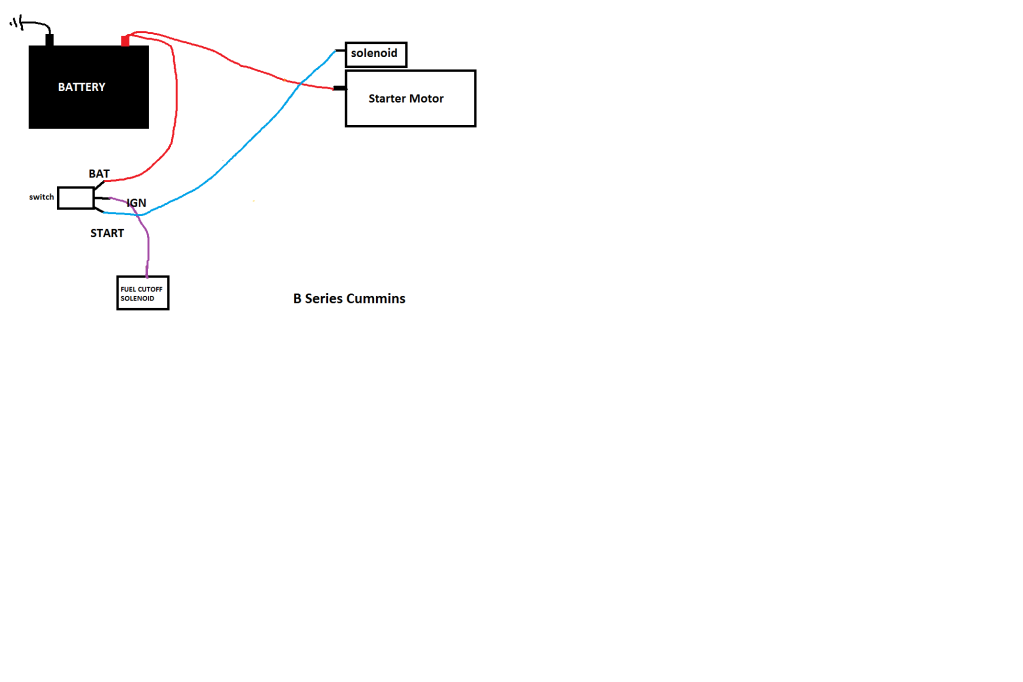
Your second wire diagram is fine. Make sure you breaker the batt feed to the switch for your max current draw.
Looks similar to mine but the principle will be the same. My fuel pump only has 1 wire, it self grounds to the pump. It just gets 12 volts from the ignition switch.
The cranking circuit goes directly to starter solenoid.
I think I will get it right, my updated diagram is pretty close to that schematic minus the Intake Manifold Heater Circuit.